SmartMachining
SmartMachining AVI Movie
Now Available For
AutoCAD 2014 64 Bit with Customer Customizable Presets For
Each Module!
SmartMachining is a revolutionary way of thinking about designing custom
cabinetry. With easy to set preset parameters, SmartMachining will add holes in
AutoCAD® solids in an intuitive way to match your company’s specifications. We have
included samples of certain industry standard boring patterns, but you can
expand on these easily. SmartMachining consists of six modules, which are sold
as one suite, for standard tasks. Each with their own AutoCAD® button
and each with their own menu and sets of parameters. Any combination of metric
or inch drawings or machining units can be selected. Please click on the icons
below for a more detailed description of each module. Presets can now be stored
as a group to facilitate the use of different shop standards for different
jobs or clients.
SmartMachining, by itself, makes applying boring patterns
easy in AutoCAD® solids, but its real strength is shown when it works in
conjunction with MillLister, Inc.’s product, SmartLister.
One of the strengths of
SmartMachining is to let your manufacturing facility create the joints and
holes you want to, without being tied to parametric predesigned cabinet
configurations by others. This is especially useful in one of a kind products.
The six SmartMachining modules are: drawer slide boring, hinge
hole and hinge plate boring, line boring, knock down fittings, doweled or Confimat™
joinery, tongue and groove joinery, and a button to remove all holes from the part. Please click on the icons
at the top of the page to get a more detailed description of each of
the SmartMachining modules.
_______________________________________________________________________________________________________
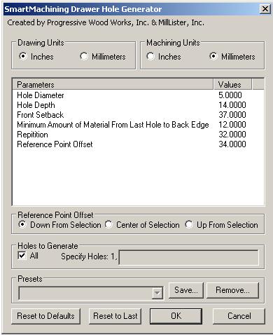
This module
allows for a line of holes to be placed horizontally on the part for drawer
slide attachment. The part, however, can be in any orientation. The offset point can work from any
location. The most frequent offset being the front bottom corners of a drawer, a
corner of a drawer face, and the top, bottom, or center of a vertical. In
order to save on machining time, only those holes that need to be drilled for
the specific piece of hardware are bored. If you do not know which hardware you
may be using, an entire line can be generated which will fit all of the 32mm
system slides. You can start the holes with any setback you would like. A 37mm
would be suitable for a standard full overlay cabinet,
however it is just as easy to make it a 12mm setback if a 25mm face frame is to
be used. When using the program, please make sure to read all the prompts as
they can sometimes change depending upon any previous machining that has been
done on the part.
_______________________________________________________________________________________________________
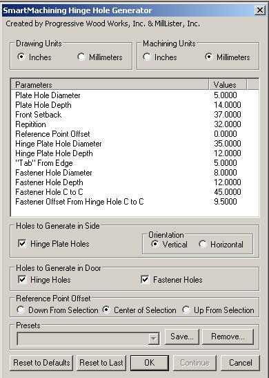
This module requires more point selections on the drawing originally, but the
user is then brought back to the menu to make minor changes to insert
additional hinges or hinge plates with a single reference point in subsequent
applications as long as the same door and surface are used.
Please note that the user can select the orientation of the hinge plates, and
choose any combination of hinge plate holes, hinge holes, and hinge fastener
holes. Even though all holes may not be selected, all reference points on the
drawing must be selected. A special feature has been added that may seem a bit
odd at first. The program will ask for the upper edge of the face and then the
furthest extent of the edge. The reason for this is that AutoCAD will select
the flat face, but if the front edge of the face has a bullnose
edge or other type of edge besides square, the program needs to know that. If
you have a straight edge, just click the same point again. This also is true
for the door. If the edge on the door is not square the program needs to know
that, again if it is, check the same point twice. This allows the user to put a
solid wood edge on the door, and then bore the door on a hinge insertion
machine, drill press or CNC machine. Even if you buy out your doors, this will
tell you where they need to be bored when you get them. Standard boring
patterns have been supplied, but each manufacture has wide range of door tabs
so please make sure you double-check the hinge manufactures specifications. A
mock up is suggested originally before that preset should be used on a regular
basis. When using the program, please make sure to read all the prompts as they
can sometimes change depending upon any previous machining that has been done
on the part.
_______________________________________________________________________________________________________
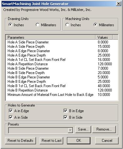
This module
allows for a wide variety of joinery and boring application. First, it can be
used for straight dowel joints. Second it can be used for
doweled joints in combination with Confirmat®
fastener joinery in one step. Third is the ability to turn on or off any
of the four types of holes created in each operation. As with
all modules in the suite, side and edge locations are non-specific. This
means that the same joinery can work on the mid horizontal and a mid vertical,
as well as on a four sided box. This module, as well as the tongue and groove module is also especially good with
odd angles and tapered pieces, just make sure your
boring machinery can handle the joints created. When using the program, please
make sure to read all the prompts as they can sometimes change depending upon
any previous machining that has been done on the part.
_______________________________________________________________________________________________________
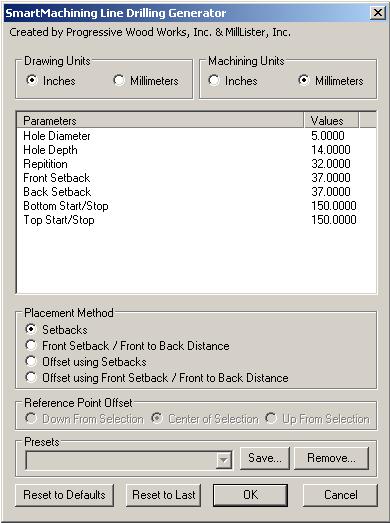
To allow
for the widest range of applications with the fastest method of selection, four
different machining options have been supplied. The first option
”Setback” relies on the setbacks supplied only. Once the face and front
edge are selected, the holes are generated to fit within that entire face. The
second option, “front hole and setback” are for those manufactures who use the system holes to mount their drawer slides, and
the relationship between the first and second holes are crucial, again the
entire face is drilled. The third option is similar to the first, and the
fourth option is similar to the second, however they allow for an offset to be
used and allows for a specific number of holes to be drilled. The offset works
both for the up and down location as well as the front to back location. This
makes inserting the line boring holes for a 12” deep shelf in a 24” deep
cabinet especially easy as no setback needs to be determined ahead of time as
the midpoint of the front edge of the shelf can be your reference point.
By selecting different parts in the assembly, any surface whether vertical, at
an angle or horizontal can be bored with holes. When using the program, please
make sure to read all the prompts as they can sometimes change depending upon
any previous machining that has been done on the part. In addition, please note
the area that can be seen as a dotted line, that describes the “face”. The use of
through dados may cause AutoCAD to redefine the “face” size and sometimes toe kick notches will change the pattern.
_______________________________________________________________________________________________________
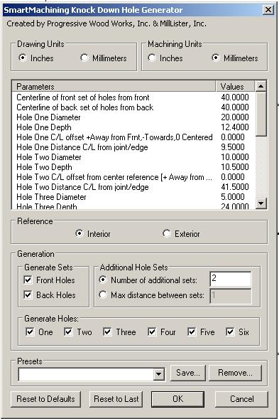
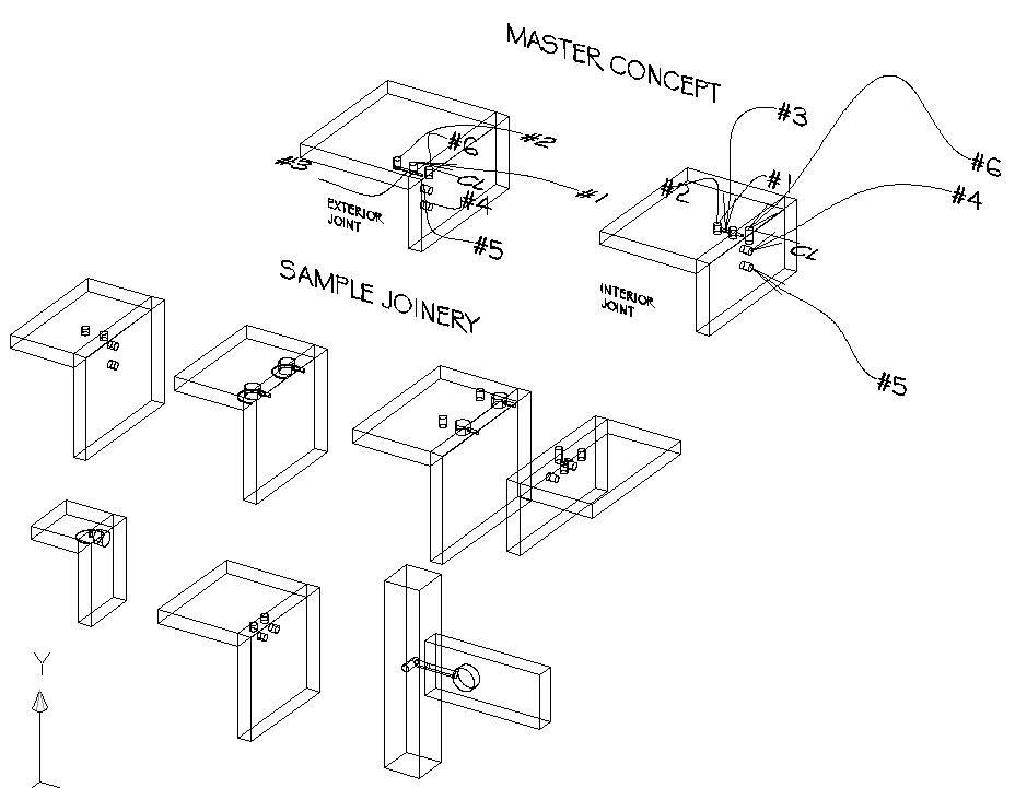
This module allows for the creation of a group
of holes simultaneously for the use of knock down fittings. While the interface
is a bit more extensive than other modules, the actual insertion of the holes
is far simpler as only two points need to be selected in the drawing. Only some
of the holes will need to be drilled for the various fittings, not all six. The
same preset feature is included, thus allowing a single set up for each type of
fitting, whether the joinery has an internal or external reference. One of the
new conceptual features in the concept of creating line of fittings based on a
front point, back point and then either the number of fittings along the joint,
or the maximum distance between the fittings. One can also create a single
group of holes if desired. A group of presets will be provided,
in addition the user can create their own easily. Please see the drawing below
for a few examples of the type of fittings that can be created, in addition to
the concept for the creation of the holes. The holes can be placed either
parallel to the joint edge or perpendicular, allowing for a wide variety of
fittings to be used.
_______________________________________________________________________________________________________
When creating a
library of cabinets frequently it will be necessary to change the size of the
box and thus the holes will no longer be where you want them. You will however
want to keep the shape of the parts and the predetermined joinery. This line
command module will remove only the holes from a solid. You can then replace
the holes as needed. You can select one or many solids at a time and then hit enter
to activate the hole removal.
_______________________________________________________________________________________________________
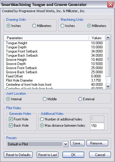
NEW AUTOMATIC PILOT HOLE FEATURE!
Many people are using tongue and groove joinery in conjunction with nested based
manufacturing. In many cases it is suggested for ease of edgebanding
and to have the CNC correctly identify the groove location and size, that
stopped dados be used. Please remember to allow for the diameter bit that will
be used to allow for enough “slop” in the joints and allow for correct front
and back start/stop points. One of the disadvantages in this type of
construction with CNC work is that it can be material thickness sensitive. The
thickness of the material has a direct relationship to the length of the tongue
as well as the thickness of the tongue. Either find
the thickness of the material you will be using and draw the solid at that
thickness and apply the machining, or else see if you can set the machine to
reference off the surface of the bed rather than the top of the material. Some trail and error may be necessary here to determine the
settings that will work best for you, your material and your machine. Please
remember that many machines will not allow you to make a groove the same size
as the bit you are using, so minor adjustments may be needed in groove width.
An automatic pilot hole feature has now been added. The user has the option of
“Interior”, “Center” and “Exterior” joint. This is the relationship of the
joint location on the edge from the side reference point selected.
One
other option that you have that may rarely be used is the offset option. In
almost all applications this will be set to zero, however there is a specific
application that uses it. If a custom bit is made with, for example, a 3.5mm
flat, a 6mm tongue and another flat, one could cut down into the spoil board
.5mm, have a 3mm reference flat and then the tongue. By placing the groove in
the board at the appropriate place, the board thickness problem for accurate
joinery is basically eliminated, as the tongue will have a known thickness.
This operation can also take place without the need to flip the part over and
do a sixth side matching operation.
In the standard application of this module the inside of the box would be correct, but the exterior may be off. It’s a design trade off. One of the other major features of this program is the ability to generate either a tongue or a groove without the need to generate the other feature. This is especially helpful when dadoing out for a back or drawer bottom, or adding a tongue on the front of a vertical for a face frame to attach to. When using the program, please make sure to read all the prompts as they can sometimes change depending upon any previous machining that has been done on the part.
_______________________________________________________________________________________________________
|
||